Balint Seeber and I were fortunate enough to work on the communications for this project. When you tell most people that you designed a deep-space uplink modulator in a couple of days, there is a good chance that they will be fairly impressed. In reality though, products like the Ettus Research USRP, the open source SDR framework GNU Radio have made this exceedingly easy. We’re just building off the work of many people before us!
Let’s talk about how this “magic” works!
Design Approach – Leverage SDR!
In order to meet the aggressive schedule and budget requirements of this project, we elected to use software-defined radio to implement the uplink. There’s basically one place people go to build an affordable SDR-based systems – and that would be Ettus Research, maker of the USRP product line. And typically when people use a USRP, they use it with GNU Radio.
For the readers who are not familiar with SDR, the USRP, or GNU Radio, I’d explain it like this: SDR allows you to implement functions that had been previously implemented in specific, tuned RF circuits in software. This in turn provides some awesome capabilities, such as:
-
Flexibility – Using the same piece of hardware to operate over multiple standards. For example, you can use the same USRP and laptop to implement the vintage uplink modulator discussed in this article or something more sophisticated like a modern satellite broadcast transmitter.
-
Rapid prototyping and debugging – Let’s face it, we all make mistakes, especially when it comes to the ‘black magic’ of wireless system design. SDRs like the USRP allow you to iterate on designs until the do just what we need, all for very low cost.
-
Community – Really, the community that has grown around the USRP and GNU Radio is enormous and grows every day. This allowed me to get in touch with experts and peers to vet implementations very quickly. Remember, there was no reference hardware we could “truth” against, so access to peer review was very important to make sure we interpreted and implemented things correctly.
Hardware and System
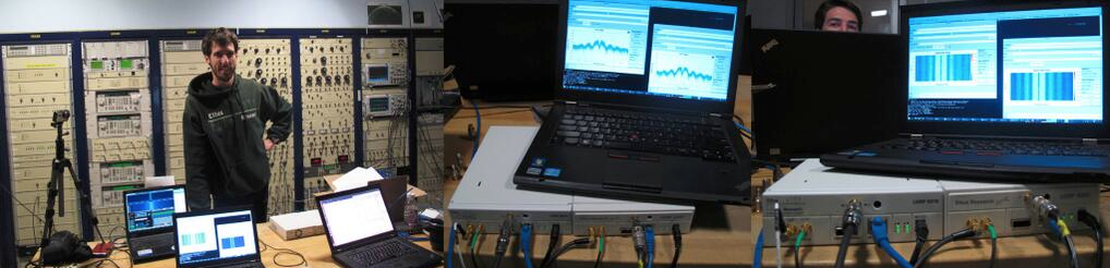
As you can see from many pictures posted by Balint Seeber, the hardware configuration is actually quite simple. It is an affordable, but very capable USRP N200 which contains an SBX motherboard. The N200 is connected to a laptop via Gigabit Ethernet. The output of the USRP (~ 2.05 GHz) is transferred to the transmitter room in the Gregorian dome of the dish via an RF-over-Fiber system. The signal drives a 400 W S-band amplifier, whose output is finally transmitted off the dish.
USRP N2xx For ISEE-3 Uplink and Downlink
We’ll touch on the feed at Arecibo in a different article. It’s quite flexible and impressive, and the staff at the observatory were extremely accommodating as they helped us put things into the right configuration for this project.
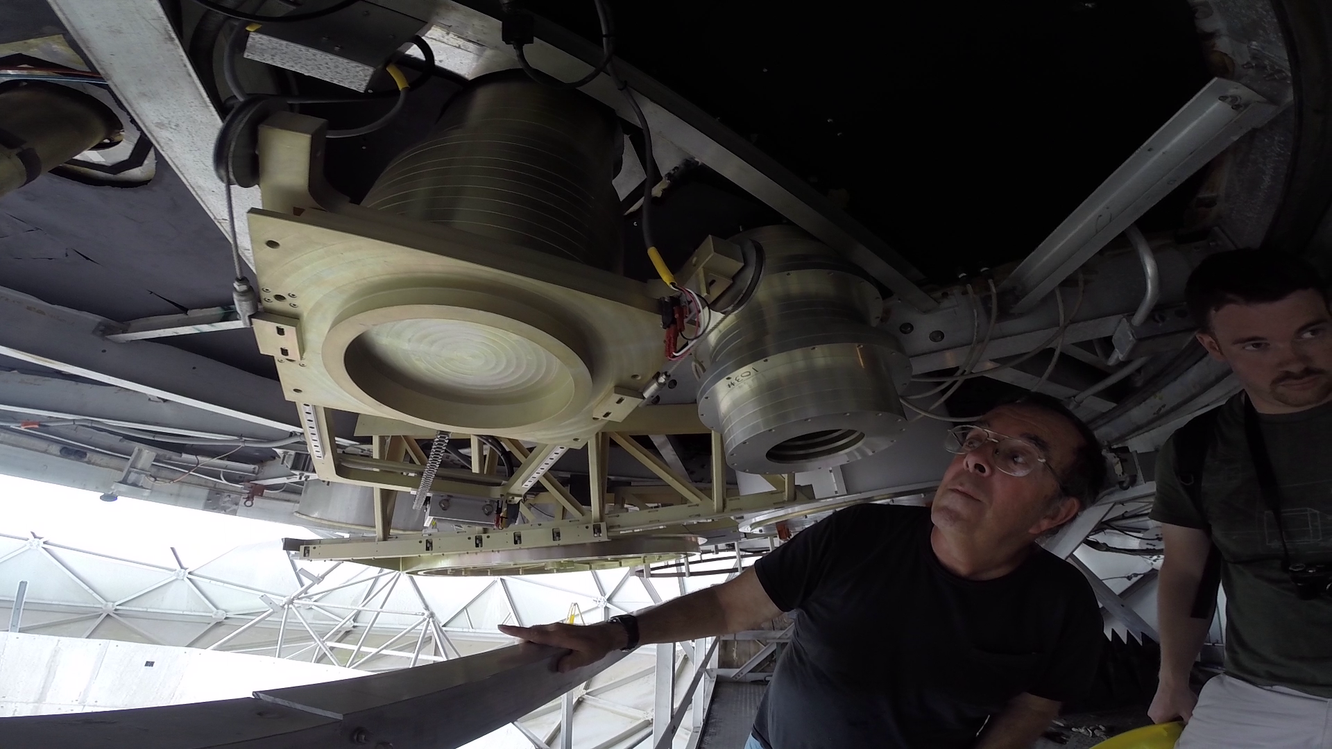
Rotary feed at Arecibo Observatory.
The Uplink Specification
Actually, one of the most difficult parts of this project was sifting through hundreds and hundreds of pages of specifications from NASA. They covered everything from the antenna designs, to the specifics of the modulation scheme, to the layout of the communications system of the ground segment! After some digging into sometimes contradictory specifications, we did converge on a modulation spec. The uplink uses PCM/FSK/AM/PM. Here’s how it works:
If you have a command you would like to send up, you generate the appropriate command sequence, which is basically 60 bits in length. These bits are fed into an FSK modulator with a center frequency of 8.25 kHz and deviation of 750 Hz. Narrow-band FSK like this is pretty standard, but that isn’t the end of the modulator chain.
In these early days of deep space communication, the designers wanted to make the receiver on the spacecraft as simple as possible. Instead of designing clock recovery circuits on the spacecraft receiver, they decide to include the clock on the uplink signal. This is accomplish by AM modulating the FSK sub-carrier with the clock signal. Thus, there is now sub-carrier where frequency represents data, and amplitude represents clock. This FSK/AM modulated sub-carrier then phase modules the RF carrier (2.05 GHz). This scheme is generally not considered to be bandwidth or power efficient. But its easy to trade power efficiency for simplicity on the spacecraft. Here’s some screenshots of what things look like at various places in the modulator chain:
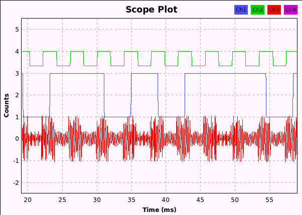
This plot shows the clock (green), random data (blue), and the FSK/AM sub-carrier (red). Note, do to small deviation relatively to sub-carrier frequency, FSK modulation is not immediately apparent, but it is clear that clock is AM modulated onto the sub-carrier.
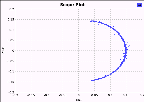
The subcarrier signal shown above drives a phase modulator. If the signal was only FSK modulated, the sub-carrier would be a continuous and the signal output from the PM would move around the unit circle with a constant radio(envelope) . However, the AM modulation from the clock produces some instantaneous changes in the sub-carrier, and in turn fluctuations in the envelop of the PM signal.
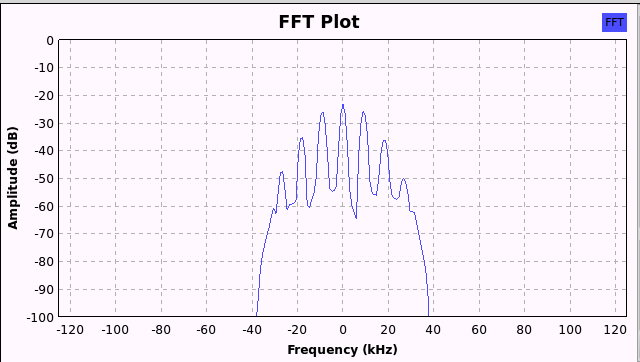
This is the spectrum of the uplink signal.
Originally, all of this was implemented in hardware, with calibrated circuits fulfilling each of the modulator functions. Fortunately, technology has been marching along for the past 30 years, and we have a much easier task than some of the original designers.
Modulator Implementation in GNU Radio
As I said, digging through the specifications, and confirming our own understanding of how the modulator should work was the challenging part of this project. Most of the functions of the modulator can be implemented with blocks from the standard in-tree modules. Truth be told, this modulator can be built in a matter of hours by someone who is relatively new to GNU Radio. Here’s the flowgraph we put together:
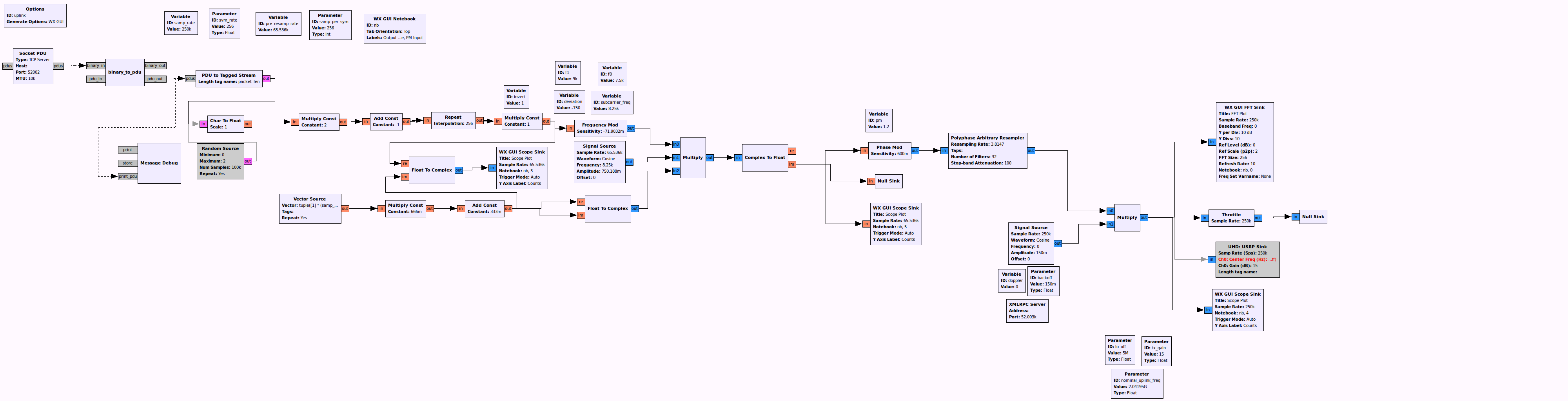
Uplink flowgraph used to communicate with ISEE-3.
Starting from the left, there are a few blocks that help us get data into the flowgraph from an external application. The Socket PDUinterface is just that, a TCP/IP socket that outputs data in frames called “PDUs”. There is one more block called “binary_to_pdu” which helps collect bits and then pass them along to the modulator in a contiguous frame.
After being converted to a stream of bits (that are represented by bytes), the data is frequency modulated at baseband (I/Q), multiplied by a complex cosine to shift to sub-carrier frequency, as well as the magnitude driven by the clock (from vector source). This AM+FSK modulated sub-carrier phase modulator, which has a pretty loose modulation index specification. Finally, the signal is re-sampled and output to the USRP through the USRP sink. Just prior to these, we apply on last step of frequency correction for doppler and clock uncertainty. The I/Q stream is then sent to a USRP tuned to the uplink frequency.
An XMLRPC client allows us to change many parameters like offset frequency and data polarity at runtime. With this, the same external application that generates the commands can also tweak parameters. We’ll discuss how this for our transmission strategy soon.
Transmission Technique – Command/Modulator Parameter Search
Now that we had a system that was capable of transmitting correct commands to ISEE-3, we had a little bit of guess work to do. There were a number uncertainties about the behavior of the space craft receiver. Ambiguous specifications on items like receive lock range, phase modulation index, and mark/space tones, left us with some uncertainties to deal with. Also, a rough link budget showed that we should have about 5 dB of margin under ideal circumstances. If we had any significant pointing errors, or there were other factors we hadn’t accounted for, there was a decent chance that we were operation near the best sensitivity of the space craft receiver. This meant we could have a marginal link with frequent bit errors.
So while we had our “best guess” at the proper command and modulation parameters, we decided to write a script to automate the transmission and modulation parameter adjustments. This allowed us to try many commands and many modulator configurations in the short contact period on our final day at Arecibo.
In the end, this strategy worked out for us. We were able to turn the modulation on on the first day we were permitted to transmit. With telemetry enabled we can begin to decode data and assess the health of the spacecraft.
Working on the Downlink
The team will continue to collect data from the downlink and assess the health of the satellite. For more updates on this effort, please see the official ISEE-3 project page.
Access to Source Code
GNU Radio is an open source community, and we are all about sharing. Sometime in the not-to-distant future, we may release a portion of our implementation. In the meantime, if you have any questions, feel free to contact me → [email protected].
Other Pictures, Resources, and More!
My Personal Album from Arecibo Observatory
]]>
- Global Position and Status Reporting with Iridium Communications
- Two-Way Communications, with legacy support for APRS transmitters
- Support for a variety of sensors – GPS, temperature, preasure, battery-sense and more
The long term goal of this project is to make it easy for people to get up and running quickly if they are beginners, or customize both the hardware and software to meet the needs of their mission if the are intermediate of advanced ballooners. With this, we hope to open the doors for more people to experiment with high-altitude balloons in a meaningful and novel way.
Initial Progress
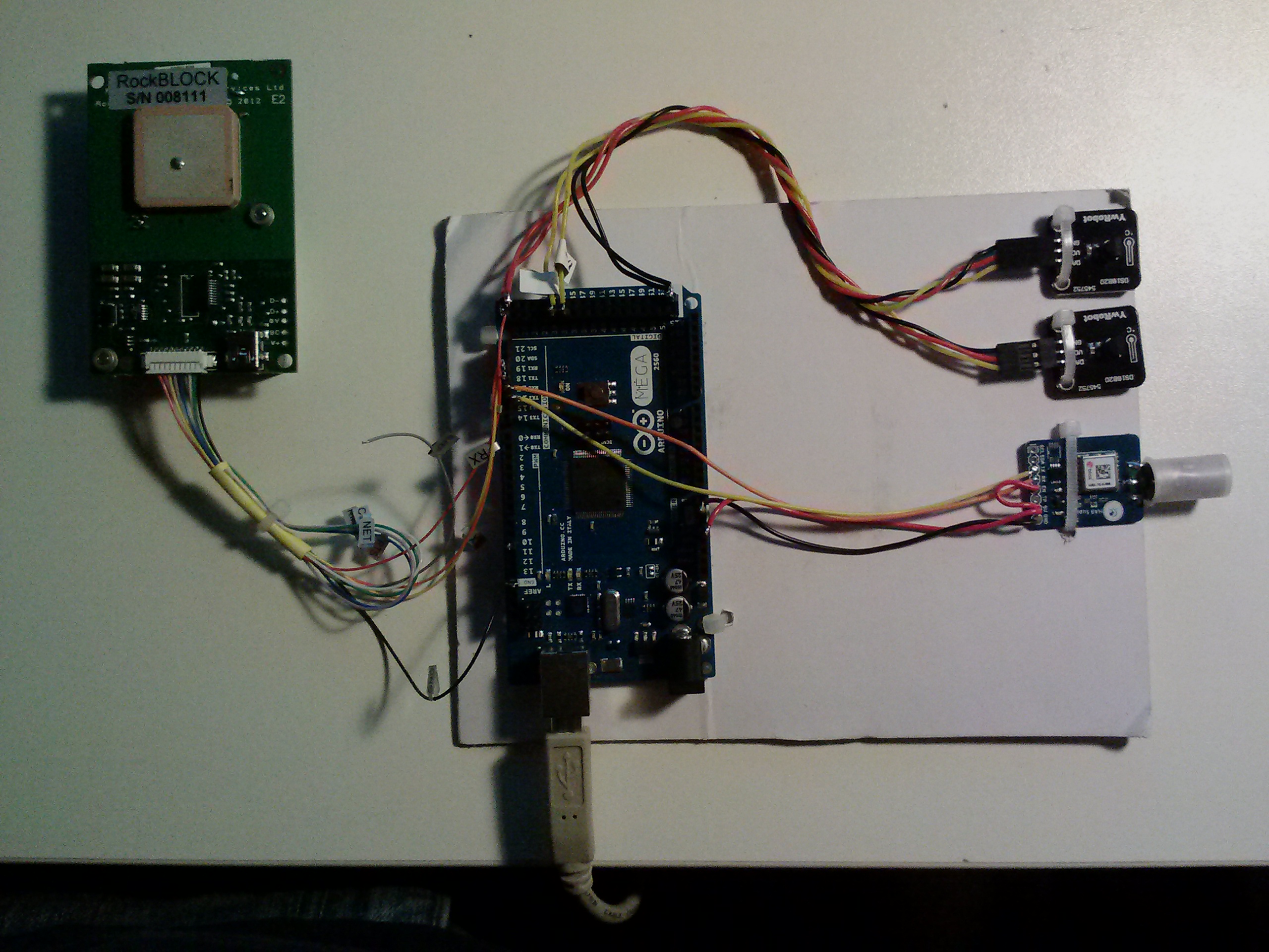
We assembled an initial prototype and have functional software that provides basic payload functionality. On the payload side, we decided to use Arduino for its ease-of-use and ubiquity. The Arduino interfaces to a few sensors, including a MAX7Q GPS, a couple of temperature sensors, and of course the Iridium modem. Over time, we hope to add support for a long list of sensors and a variety of embedded targets – both larger (ARM/Linux based) and smaller (for low-power/light-weight missions). For now though, this is a happy medium to get everyone off the ground (pun intended).
On the ground side, a Python script interfaces to an email server through SMTP and IMAP. This is how we exchange messages between our application layer (where we product commands and process incoming data), and the payload. This Python application should be fairly easy to modify, if your mission needs . Over time we will post tutorials on how to a modify this ground station software, and the payload software to your liking. In essence, this is a GUI or command-line application that will allow you to control your balloon from anywhere in the world.
We have tagged an initial release of the software (admittedly, without much documentation). You can find the code here:
https://github.com/jmalsbury/
Also, here is a picture of the prototype:
We plan to get everything packed up and experiment with some launches in the coming months.
More Information, Feature Requests, and Volunteers
If you are interested in helping out with this project, submitting feature requests, or have any general questions, please contact John Malsbury, [email protected].
]]>- Automatic position reporting with settable intervals, and on-demand updates
- A common set of commands to control GPIO for functions like ballast cut down, triggering a camera, etc.
- More commands to read ADCs, a suite of sensors, etc.
- Interfaces to positioning servers like APRS.IS
- Automatic updates on social media (Facebook, Twitter) so everyone can follow the balloon you worked so hard on!
- Most importantly: This will provide an infrastructure for people to automatically add their own, custom functionality in an end-to-end system.
This is a work in progress, but I do expect rapid progress.
It’s late and I’m tired. But those of you who are interested can find some basic code that will send and receive Iridium messages through an Email server. More to come soon!
https://github.com/jmalsbury/allaloft
Please shoot me an email if there are any features you’d be interested in seeing or you might like to help out!
]]>

The RockBlock
For the sake of this post, we will take a closer look at one service provider, Rock 7. They sell the RockBlock, which is basically an Iridium 9602 provided in a convenient USB-power assembly (board-only or ruggedized). They also have done a nice job of simplifying some of the archaic looking documentation that other Iridium service providers have put together.
We’ll talk about the hardware in some other posts. I’d like to get to my point on the pricing structure. Looking at the fees per byte, this scheme is actually pretty reasonable. Compared to alternative service providers, this structure favors hobbyists or engineers on smaller projects. However, there is an important thing to note:
YOU WILL USE 1 CREDIT, EVEN IF 0 BYTES OF DATA ARE TRANSFERRED IN THE SBD SESSION.
That’s right. Even if no data is sent to or from your mode, you will still be charged. Many hobbyists/engineers pick up the modem, expecting that they can poll with frequency SBD sessions, only to find that they burn up their credits quickly. Another fact, which isn’t quite clear, is an SBD session that transfer a single byte will also consume 1 credit. It might be better if Rock7 adjusted their language to say, “The minimum billable byte count for each SBD session is 50 characters (1 credit).”
How does Iridium/Rock 7 justify this pricing structure?
In actuality, this pricing structure is somewhat legit. Some developers have the misconception that they have not taxed the system if no data has been passed to or from their modem. In actuality, each and every transaction consumes precious satellite bandwidth, even if no payload data in transferred. The modems/satellites have to do things like negotiate TDMA slots, acknowledge packets, and talk all the way up the network stack just to check for messages. So the bandwidth consumed for no data is very comparable to the bandwidth consumed for a full-length packet.
How expensive will my M2M gadget/widget/project cost to operate?
Let’s assume we have some widget mounted on a truck.

We want the widget to report position every five minutes, and check for incoming commands from a control center every minute. It would behoove us to reduce the data in standard NMEA GPS strings to some binary or otherwise reduced format, so we fall below the 50 byte threshold and minimize the credits per outgoing report. Also, it is worth noting, that when an SBD session occurs, it will automatically check for incoming messages. So, if we align our outgoing GPS message to our command polling interval, we can avoid an extra SBD session. In this scenario, we’re looking at a 1-credit SBD session every minute if no commands are sent from the control center to the modem. This translates to about $4.80/hr – not so bad. But if you consider that many of these system go through significant duration test as command and control system are developed, or use multiple devices this can really add up – especially for hobbyist projects.
So, how can we avoid some of these costs?
Drop the polling architecture, use SBD Ring
If you perform an SBDREG when you initialize the modem, the Iridium system will keep tabs on your units position and status. Also, when a new message arrives on the ground station segment, an “SBD Ring” signal will be sent to the modem. This produces a pulse on the digital Ring output, and also a string output on the serial port. At which point, the MCU/processor connected to the modem would perform an SBD session.
It is worth noting, the SBD Ring has not been 100% reliable in my experience. Also, from what I’ve been told (but no observed myself), is the SBD Ring can be inserted anywhere in the UART output of the modem, even if it is in the process of responding to AT commands. So, it is still a good idea for to poll, albeit at lower frequencies.
Don’t poll for data, just check when you have outgoing messages.
Pretty simple. Since every transaction involves both transmission and reception anyway, the Iridium system is nice enough to downlink any pending messages while we are uplinking our own. If you have a mobile that is consistently sending messages, you may not need schedule additional SBD sessions to receive.
Use my Iridium 9602 Emulator
At least, this works in the prototyping phase. If you’re working to developed some microctronoller code to talk to the modem, or the “server-side” system to work with your M2M system, you can leverage the free and efficient bandwidth of the internet. My emulates the AT command parser on the 9602, and will send/receive properly formatted messages via email. You can find more information about my emulator here.
]]>
For those of you who are not familiar with the work… I developed a GNU Radio library called pre-cog in this past Fall. This was originally prepared for a tutorial on cognitive radio at DySPAN 2012. The pre-cog framework was built as a demonstration of a few capabilities of GNU Radio and the Ettus Research USRP. Some of these capabilities:

Software-Based Packet Radio with GNU Radio, gr-extras, and my framework, “pre-cog”
- USRP Timed-commands and tuning functionality (useful for things like frequency hopping)
- Timed-streaming with
- GNU Radio – Stream-tags
- GNU Radio – Python blocks
- GNU Radio – Async. Message Passing
In short, I was trying to show that it is possible to implement both PHY and MAC functions within GNU Radio, while taking advantage of advanced driver features of the USRP family. Some would argue that MAC functions don’t belong in GNU Radio. On some occasions I might agree. However, I still think there is some value to integrating this in GNU Radio, and in-turn, GNU Radio Companion. The main appeal is the ability to modify things in a graphical environment, which makes it easy for students and tinkerers to experiment with different access schemes (CSMA, TDMA, FHSS, etc), physical layer designs, and MAC-layer functions. Essentially, I’d like to create PHY/MAC “Legos”.
What it looks like now…
I did my best to modularize my blocks, but include enough functionality in each block to create clean and easy-to-understand applications. The simplest example is a half-duplex, single-carrier CSMA radio with ARQ. This can be seen in this video:
There are also blocks available to implement TDMA and FHSS. These PHY blocks can replace the CSMA PHY. The same is true for the MAC layer blocks. Currently there is only the “Simple MAC” block.
Next Steps and What I’d Like to Accomplish
After proving the basic idea through this simple framework, and talking to a few people, I’ve decided that it may be worth more effort. The community has provided some indication that a more thorough implementation would be valuable. Here’s an obvious list of improvements/changes:
- Update the blocks to use new PDUs in GNU Radio
- Re-write blocks in C++
- Come up with a cleaner mechanism to pass meta-data around.
- Improve documentation and examples. Make some tutorials.
My ultimate goal here is to spend my time producing something valuable for the community. Thus, I’ve typed up this post to solicit feedback from any students, professors or hackers using the framework. What should change from an architectural standpoint? What blocks and functions are most useful for you? In general, what should I be doing differently?
Also, most importantly… pre-cog is an awful name.. What should I call the official project once I’ve kicked it off?
You can connect with me through my social media links (to the right), or at [email protected].
]]>Iridium Integration Challenges
As mentioned in our previous posts, we are beginning to develop more sophisticated payloads. One of the features that we are adding is two-way global communications with Iridium. As payloads become more complex a number of issues pop up. First, the total labor required to design, program, and test the payloads. But the increase in effort is non-linear. Every interface, every additional programmer, and every additional component adds new challenges. In other words, the integration work for this payload is going to be greater than the sum of its parts.
Starting on Iridium development, several issues became apparent:
- It would be useful to enable multiple developers to develop with system that are effected by the Iridium modem, or GSS-side functionality – but we can’t afford to purchase hardware for each and every person.
- The integrated of the antenna on the Rockblock makes it difficult to develop anything indoors. The margin of the 9602 already appears to be pretty low, and simply won’t work unless the unit is outside with the antenna pointed up.
- Last but not least, my misunderstanding of the Rockblock fee structure . Some ambiguity in their language could lead someone to believe that you are charged a “credit” every time you send a message with SBDIX. In actuality, I thought we would be charged by bytes transferred.. but its much worse than that. With the Rockblock, you are charged for EVERY SBD session, even if you do not send or receive a message.
One solution to item (3) is to look into having the modem switched to service from N.A.L., but to be honest I’m not sure that will be much less expensive. It’s also possible that some contract prevents using a Rockblock modem on N.A.L. Service.
Iridium System Emulator
All of these factors motivated me to write an emulator for the Rockblock (Iridium 9602). Prior to doing so, I did a search on the web, and was very surprised to find that such a solution did not exist. This emulator, written in Python, does several things:
- Emulates the serial communications behavior of the 9602. Currently, most of the AT commands are implemented, so you can run through the process of writing message and completing SBD sessions (i.e. ‘at+sbdix’). It even uses a virtual coin-toss to simulate the frequency session failures.
- Will read and write correctly formatted e-mail messages to a e-mail account specified for the modem. In this way, whole thing emulates the GSS. You can send e-mails to the test address just like you would send them to the Iridium SBD address, and this virtual modem will receive those messages on a successful SBD session.
- And more stuff that’s not as important.
Let me show some illustrations on why this is useful. Looking at the real-world communications architecture will add some insight:
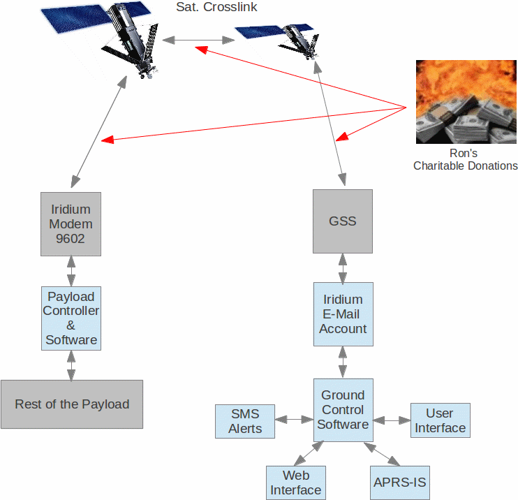
In the diagram above, all of the software/embedded components we are interested in develop are painted a light-blue color. To properly develop and test these software components across the operational envelop, we simply need to send a lot of test messages. These test messages can be actual, costly SBD sessions with the real hardware. Or these test messages can now be produced with this 9602 emulator. In other words, our development system now looks like this:
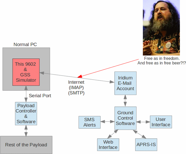
There’s a little humor in there for the open source junkies. Anyway, with this system, we can vet a good portion of our system design before we ever send any data over the Iridium system, or incur costs from Rock7Mobile. Of course, we will be doing some testing with the hardware as we go through the process as well. For certain portions of our validation campaign, there’s just not replacement for the real thing.
Where can you get the emulator?
Another benefit to developing this emulator, is that people can experiment with the overall communications concept (SBD ↔ E-mail), before buying hardware. In principle, this means we could expand our development team without needing to send more hardware. Of course, you are free to use this for other projects that are unrelated to high-altitude ballooning. My hope is that this will save some other people some time, frustration and money.
If you are interested in running the code, please see http://github.com/jmalsbury/virtual_iridium to download the code and find some limited documentation. This emulator requires Pyserial to be installed. I’ve only tested it on Linux, but I did what I could to keep in OS-agnostic.
Here’s a short snippet of how to download and install the software:
git clone https://github.com/jmalsbury/virtual_iridium cd virtual_iridium/python python Iridium9602.py -d /dev/ttyUSB0 -u [email protected] -your_password -i imap.gmail.com -o smtp.gmail.com -r [email protected] -m EMAIL |
Of course, you need to adjust the parameters to your liking. You ‘-d’ specifies the serial port to use. This can be a virtual serial port that connects the emulator to another application on the PC.
This is a work in progress. I am likely to put more effort into documentation, bug-fixes, and functional refinements if more people are going to use it. [email protected].
Cheers!
]]>Mission: Global, Two-Way Comms
While APRS has served as the primary tracking system on our previous missions, the idea of having two-way communications capability in all geographic areas is appealing. We have investigated satellite communications for our future missions. Starting out, we considered several services, including:
- OrbComm
- Globalstar
- Iridium
After talking with fellow balloonists and evaluating the options, we decided Iridium was the most promising solution to start experimenting with. The system seemed to be a best compromise of afford-ability, coverage, and message latency.
More About Iridium
If you want the full scoop on the Iridium system, it’s probably easiest for you to check out this Wikipedia article. However, we can sum up the basics here:
The constellation includes ~66 satellites that are in low-earth, nearly polar orbits. The satellite are arranged in 6 orbital planes to provide continuous coverage across the globe. Some satellites are currently non-operational, and there are a few “holes”.
Iridium Constellation
The system implements a FD/TDMA scheme. Each satellite produces 48 spot beams. In each beam, the satellite can assign both a frequency and a timeslot for user equipment (our modem) to communicate. When the modem powers up, it communicates on a random-access uplink channel to receive this frequency and timeslot assignment. When the user sends a message, the modem communicates on its assigned timeslot and frequency.

Iridium – TDMA Frame Structure
During a successful short burst data session, the user equipment transfers a message to a satellite in view. This message arrives at the satellite but doesn’t stop there. It is passed along to other satellites via Ka-band cross-links. Eventually, the message will arrive at a satellite that has line-of-site to a ground station. The is transferred to the ground component, where it is delivered to the end user via e-mail, TCP/IP, or an HTTP session.
Iridium Hardware
Generally speaking, Iridium designs modems that are OEM’d by partners like N.A.L. Research, Quake, or Rock7Mobile. These partners in turn structure their data services so you, the user, can pay monthly and/or data usage fees. Each vendor structures things a little differently. There are several models to choose from, but one of the lightest-weight versions is the Iridium 9602.
Rock7Mobile has done a nice job of packaging the 9602 on what is a glorified breakout board. We’ve chosen to use their “naked” board, which offers USB connectivity via FTDI chip, as well as straight serial. Their data plan is also attractive because you do not have to pay an activation fee, and you do no have to pay the monthly fee if you do not use the modem.
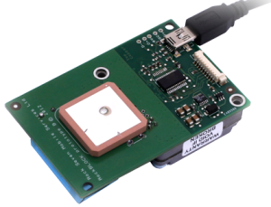
The RockBlock
Making an Iridium Modem Sing
We will provide a more detailed look at this on our next post. Essentially, the modem connects to a microcontroller or computer with a serial interface. It accepts commands just like the old dial-up modems, but uses a short-burst data session to transfer the data to the satellite constellation. The basic process for sending a message through the modem is as follow:
(via serial console 19200, 8-bit, no-parity, 1 stop bit – modems may be configured for flow control but you can turn this off)
at+sbdreg //optional, registers the modem with the network for message alerts at+sbdwt=hello world //write text string to mobile-originating buffer at+sbdix //initiate short-burst data session |
And that’s that… It may take anywhere from 5 to 30 seconds before you see a response from the modem. It will return a comma-delimited string of several numbers. The first number is a return status, and if you see a ’0′,’1′, or ’2′, the short-burst data session was basically successful. The message will be delivered via e-mail, or whatever mechanism you selected in your Rock7Mobile configuration. While you were transmitting a message, if there was a message queued for you modem, it will also download that.
You can read back a received text message with:
at+sbdrt //read text message from mobile-terminating buffer This is a test message |
More to follow!
]]>
Upload APRS Frames to APRS-IS – Part I – Learn how to get access to APRS-IS
Uploading APRS Frames to APRS-IS – Part II – Python application that uploads frames…

]]>
I will be helping the group with some payload and communication system design. I also thought that a better website and a comprehensive marketing strategy would help this group with their mission. We’ve got some pretty ambitious things planned, and I think it will excite a lot of spectatres.
Anyway, here’s what the site currently looks like:
]]>
